While our latest software is compatible with all revisions of the Bad Ass Controller product line, there are some new features that are only available on the BAC V that affect wiring and accessory compatibility:
New output driver chip with expanded protections and high-side drive support
Opto-isolator for inputs 0-3
Expanded storage capacity
Expansion port for FX45 breakout board
There are several ways you can tell which revision of the controller you have:
Label
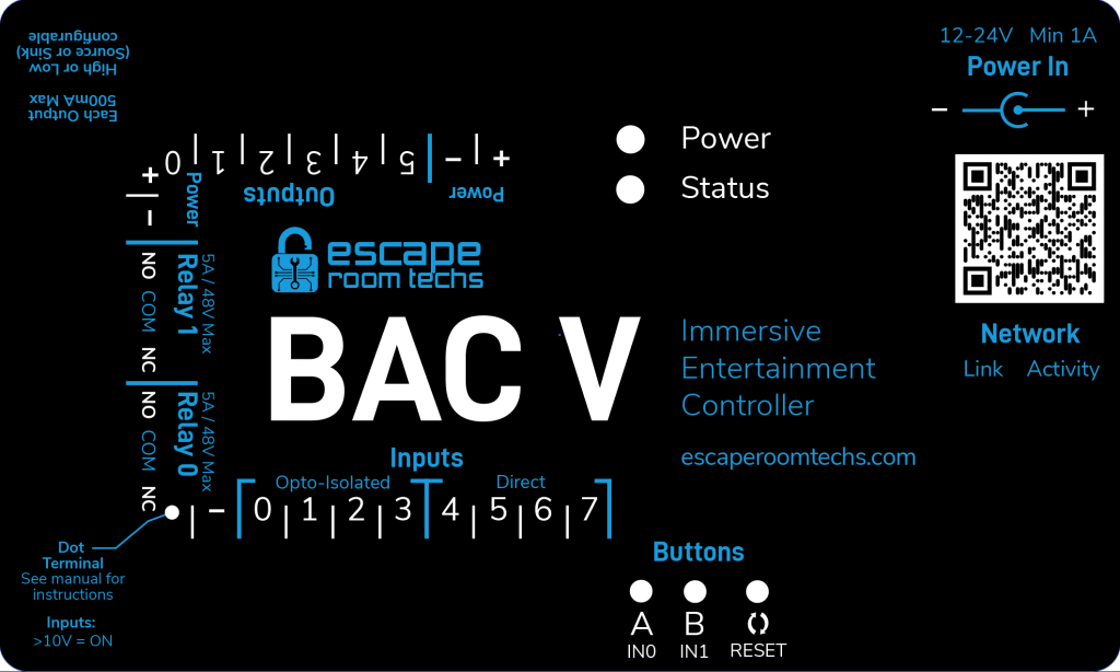
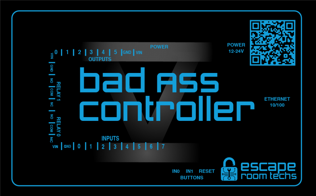
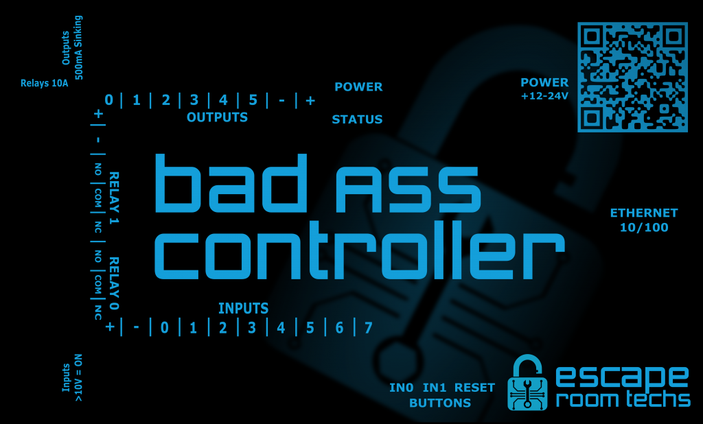
The label on the top of your case will help you distinguish your revision easily. (There may be small differences from these pictures, but you are looking for the controller name in the center and whether a V is present.)
BAC V – Rev 6 (Serial Number 4000 or later)BAC V – Rev 5 or Rev 6 (Serial Number 3999 or earlier; note V numeral in background)Original Bad Ass Controller (Rev 1 through Rev 4)
Part Number on Main Circuit Board
You can determine your revision by the part number on the main circuit board. If you have an FX451 circuit board, you have a BAC V. If you have an FX450 circuit board, it is the original Bad Ass Controller.
You can tell the exact revision of your controller from this board as well – it will be molded into the circuit board in faint green text, typically in the upper right side.
Expansion Port
If you have a 26-socket expansion port on the right side of your controller, you have a BAC V. The original BAC did not contain this port.
The BAC supports two different modes for its outputs.
In Low Side switching, the BAC will connect the output to GND (0V) when the output is on, and will disconnect the output entirely to interrupt the circuit when te output is off. This is similar to how many PLCs and industrial controllers work, and can sometimes have benefits for reducing interference when a device switches on or off or for some special scenarios. You connect your device’s positive wire to the BAC’s +12V pin, and you connect its negative wire to the output.
In High Side switching, the BAC will connect the output to +12V when the output is on and Ground (0V) when the output is off. This is how most intuitively expect the outputs to work and matches the behavior of other microcontrollers, like an Arduino output pin. You connect the output to the positive wire of your device, and connect its negative wire to the BAC’s GND.
Does my BAC support this feature? If so, what is selected by default?
Versions of the BAC prior to the BAC V shipped with Low Side switching as the only option. The newer BAC V allows you to switch between both modes.
By default, for BAC V controllers with serial number 4000 or higher, High Side switching will be enabled at the factory; earlier serial numbers may be set to either high or low side switching. Performing a full factory reset may switch your controller back to Low Side switching.
You can easily check how each input is configured and switch the mode using BAM. Each output can be configured independently, so you can even mix and match if necessary.
Download and install Escape Room Techs BAM
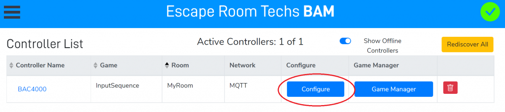
Locate your controller in the list and press the Configure button.
3. Select the Hardware tab.
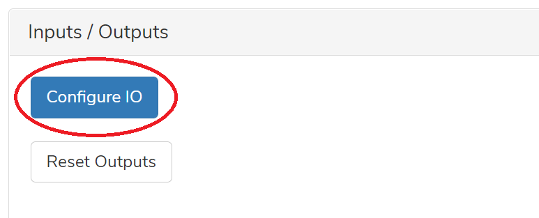
4. Scroll to the bottom of the page and locate the Inputs/Outputs panel. Find and click the “Configure IO” button.
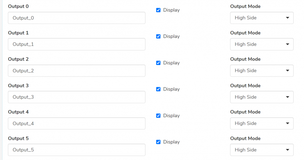
5. In the new page that opens, scroll down to the Outputs in the list. For each output, there is a drop-down selection on the right; use this box to select the desired mode.
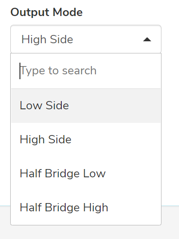
The configuration shown above is the factory default. You can also select Low Side, along with two Half Bridge options that are specialized and only used for certain motor control scenarios:
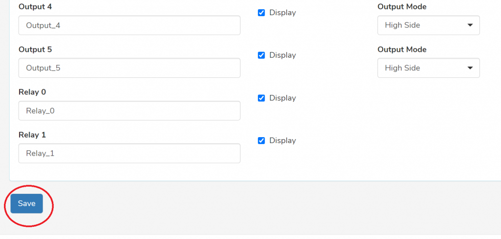
6. When you’ve finished making changes, scroll to the bottom of the page and click Save.
7. Power your BAC off and back on for the new settings to take effect.
One of the most common goals of an event on the BAC is to cause an action to occur elsewhere. This typically is accomplished by completing a circuit to supply power to some other electrical component, like a magnetic lock or a light.
The BAC offers two ways to control external devices – a relay and a digital output. Since both can be used in similar scenarios, the differences can be pretty confusing at first glance!
Digital Outputs
Think of digital outputs as a computer-controlled power supply.
The digital outputs (on the top row of the BAC, numbered 0 through 5) directly supply power to external devices using the same source power supply as the controller itself.
Depending on the revision of the BAC you have and the configuration in BAM, these may be “high side” (each output replaces the + terminal, and the other wire connects to GND) or “low side” drivers (each output replaces the – terminal, and the other wire connects to +12V). Refer to the BAC manual for details on how to wire them up… but in both cases, the key takeaway is that they share the power supply with the BAC itself.
Unlike Arduino devices, where digital outputs can only safely supply a tiny amount of power at a low voltage, the BAC’s outputs are higher power. They operate at the supply voltage (typically 12V) and can be directly connected to many external devices! Just make sure your current draw needs to stay below the limit indicated in the BAC documentation (typically 500mA at 12V per channel), and your total current consumption has to stay within the maximum capacity of your power supply.
The advantage of these digital outputs is that they are easy to understand and use – just wire a device directly to the output and it gets power when the output is on, and has no power when it’s off. They are also completely silent during operation.
The disadvantage is that you are limited to the same output voltage your controller is operating at (typically 12V), and that you cannot draw more than 500mA (fine for small cabinet mag locks, but potentially an issue for larger door-sized locks or other high current props).
The key takeaway is that these digital outputs are electrically connected with the BAC’s control electronics. That means that electrical interference from devices connected to them could potentially affect the BAC (although we include lots of protections against this happening), and it also means it isn’t always appropriate to use these outputs to control other props that have their own power supply.
Relays
Think of relays as a computer-controlled switch.
What is a relay?
The term ‘relay’ dates back to the very beginning of electrical communication, where early engineers needed to solve the problem of how to send telegraph signals across the country. Wires have resistance and signals degrade over long distances (a problem we even have to contend with in escape rooms!), so there needed to be a way to connect different circuits together to resupply new power every so often into the telegraph network, “relaying” a signal from one circuit to another.
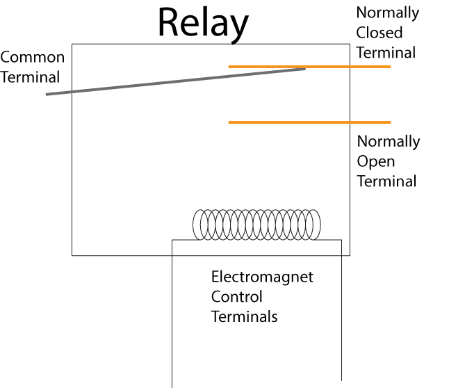
The solution that was developed is very similar to what we still use today! Relays are switches controlled by electricity; when they are turned off, the Common terminal is connected to Normally Closed, and when they are turned on, the Common terminal is connected to Normally Open.
The aspect that makes relays most useful today is that the circuit being controlled is completely electrically isolated from the circuit doing the controlling. The switching happens by turning on a small electromagnet: this attracts and pulls a piece of metal from one contact to another, physically changing the switch’s state. It’s exactly like a physical switch, except with a magnet operating it rather than your hands.
How do relays work? You can think of a relay conceptually as a flappy piece of metal, switching between two contacts called “normally closed” and “normally open”. When the relay is unpowered, a spring causes this metal to rest against the normally closed terminal:
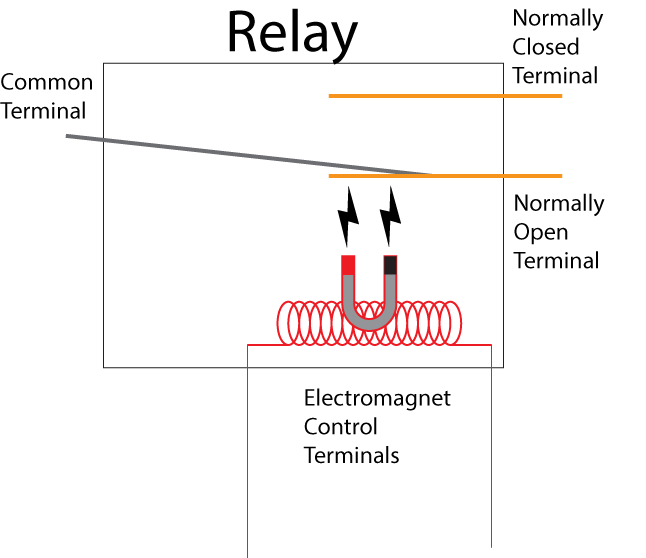
When you power the relay up, the coil acts as an electromagnet, pulling the flappy metal towards the Normally Open terminal and switching the circuit:
As you can see, there is electrical isolation between the controls and the terminals. A fault in the circuit the relay controls wouldn’t affect the control electronics, because they are separated by air and magnetism inside the relay module.
When would I need a relay instead of a digital output?
There are several situations where a digital output won’t be sufficient and you’ll need to use a relay:
You need more output current than the digital output can provide. This typically happens when controlling a large door magnetic lock, which often draw between 650 mA and 1A.
You need a separate power supply or you need a different voltage. The relay is entirely isolated from the main circuit, so you can use any power supply you prefer. The contacts are rated to handle a large amount of current (the relays themselves are rated to 10A and 125V, but we recommend you not exceed 2A and 24V in escape room applications).
You are controlling a pre-existing prop or signaling an external system. If you have a prop from another vendor, it’s safe to switch its power supply using the relay without causing any unintended effects caused by sharing power supplies between the prop and the BAC. The relay can also be used to simulate button presses or other switch closures for other controllers; this could be used to safely signal a 5V input pin on an Arduino, for example.
You are out of inputs. Even if a digital output would be sufficient, you can wire up a relay to achieve the same goals and get two extra outputs without resorting to an FX60 or other expander. In this situation, you would use the + and – terminals from the BAC’s connectors to access the same 12V power supply being used to power the BAC. You lose the electrical isolation benefits, but in many applications the convenience is worth that tradeoff.
What are the pros and cons of a relay?
Pros: The relay is isolated from the main circuit, so it’s safe to use the relay to control external devices with different power supplies or power requirements. The relay can also handle much more current than the normal digital outputs.
Cons: Relays make a soft telltale clicking noise when they switch, which can occasionally be problematic in some escape room applications by telegraphing to players that something has changed in the room. They also are mechanical devices, so they can eventually wear out if switched repeatedly (although we use high quality Panasonic relays in our products to minimize the chance of this occurring). They are also large, so only two relays fit in the BAC case.
How do I wire up a relayas a switch?
Simply insert the relay in series into your circuit as if it were a regular switch. Wherever you would normally connect a switch, connecting COM to one terminal and either NC or NO to the other.
If you want the relay to connect (close) the circuit when it’s on and disconnect (open) the circuit when it’s off, connect to normally open. (Usually used for activating special effects or solenoids.)
If you want the relay to disconnect (close) the circuit when it’s on and connect (close) the circuit when it’s off, connect to normally closed. (Usually used for magnetic locks which should be locked by default until the player solves a puzzle.)
It’s okay to switch either the high or low side for most escape room applications – we recommend whichever side your BAC is configured to switch for its digital outputs for consistency.
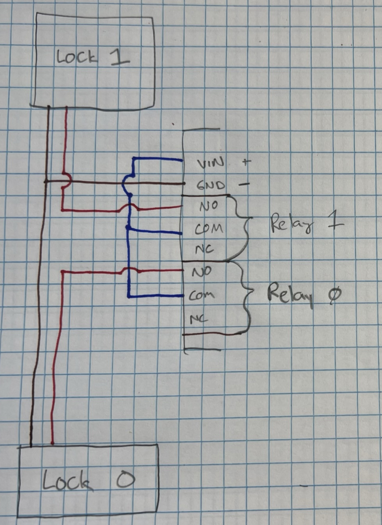
How do I wire up a relay as a spare digital output?
If you just want to use the relay as an extra digital output, you can source power from the + and – terminals as shown in this diagram:
This small-sized magnetic lock is ideal for keeping drawers, cabinets and other props closed until players have solved a puzzle. Powered by 12V, the lock retains the armature plate as long as power is applied, and the lock is released when power is removed.
Our high-quality locks are manufactured by a trusted partner to our exacting standards, and feature an internal MOV protection component that helps protect other circuits from electromagnetic interference caused by the lock switching on and off.
We include detailed installation instructions, all necessary mounting hardware, and a helpful template for drilling holes in your prop.
This lock’s electrical connection consists of a ~4″ pigtail with bare wires. Uniquely among vendors of magnetic locks, we can optionally include a no-solder lever splice connector that can be concealed in a player-inaccessible area and used to extend the wire to connect to your BAC, getting you up and running quickly!
If there is not enough space in your prop to conceal a lever-based connector, contact us to request a customized wiring harness professionally constructed with solder splices reinforced by heat-shrink tubing.
Specifications
Lock body: 80mm x 37mm x 24mm Armature plate: 70mm x 33mm x 10mm Holding force: 60kg / 130lbs Current consumption: 110mA typical, 400mA peak Weight: 0.6kgs Certification: CE
This is what you should be using. Low voltage wiring by definition is less than 49V. For our purposes, we’ll be dealing mostly with 24V, 12V, or 5V. Using a lower voltage has several advantages, but the most important here is that it’s safer. A simple touch of an AC circuit is enough to burn you, make you jump, or kill you. Low voltage is much more forgiving. You can touch 24V with dry fingers all day and not notice it. DC circuits are usually isolated too, so no path to Earth to shock you either. There is much less ‘force’ behind the electricity (analogy works for this case). Therefore, when someone takes apart your prop, breaks the glass, etc., you are not exposing them to a lethal situation. That is not to say you can’t die from DC, you can. Anything that reduces resistance like a cut or moisture can make DC deadly quickly. Which is another reason to keep current limited in your circuits.
What we are officially trying to do here is fall under Class 2 wiring in the NEC (National Electric Code). If you can do all your work in Class 2, that greatly reduces the fire initiation capability and shocking hazard. This level of protection is provided by the power supply you are using to drop your AC voltage to DC. If it’s a Class 2 supply, then it is limiting the power for you and making your circuits safer. Electrically, Class 2 for us means 100VA (or 100 Watts to keep it simple) at 24V and 60W or 5A Max for 12V and 4.1A max for 24V. Look at the chart below for wire size guidelines and limits.
Voltage
Current
Power Limit
<=2 Feet AWG
10 Feet
12V
5A (max)
60W
24 AWG (2.1%)
14 AWG (2.1%)
12V
1A
–
24 AWG (.8%)
20 AWG (1.7%)
24V
4.1A (max)
100W
24 AWG (1.8%)
16 AWG (1.4%)
24V
1A
–
24 AWG (.4%)
22 AWG (1.3%)
How to use this chart: Once you have determined your system voltage, the first line shows the maximum current and power that circuit can provide. Then choose the wire gauge (AWG) according to how long your run is. The number in parenthesis is the percent voltage loss, for a 12V system, each 1% is .12V. For a 24V system, each 1% is .24V loss.
Most cabinet wiring can be done with 24 AWG because of the short runs, but I personally am a fan of 24VDC and will do my wiring with 22 AWG all around because most items in an escape room don’t exceed 1A. If I have a long run (10ft), I will either run 20 AWG or double up the 4 conductor wire into 2 conductors (yes, that works). If you are a 12V fan, I’d run everything in 20AWG. If you are exceeding 1A, then increase gauge accordingly.
So which voltage should you use? 12V or 24V are the most common industrial voltages. 24V is the most versatile and it does have the ability to supply more power when required and losses are less. Also, wire gauges can be smaller (read cheaper, less copper) when using 24V. 12V is fine for smaller rooms or if you have some props that only work on 12V (like LED strips). If you know what you are doing, you can mix as required. 5V should NOT be used outside of a circuit board. It is not an industrial control voltage. It is a common power supply for electronics, but best practice is to keep all 5V signals inside the electronics board (or immediate wiring area) and use 12V or 24V for external, longer wires, like power and switches.
This means don’t run your 5V Arduino/Raspberry Pi/other hobby board I/O pins to the outside world. They are too fragile and too sensitive. More on this later.
Basic wiring
Many of the same rules that applied to AC wiring apply to DC wiring. They are just good practice all around.
Restrict, tether, mount, strap, etc. your wiring. Keeping wiring from getting yanked out of their termination point increases safety a lot.
Use proper boxes. Don’t leave a connection in midair with wire nuts on it.
In a box with mixed voltages (AC and DC), keep the AC as far from the DC as possible. You should be able to draw a virtual line down the path where they are kept separate. Generally, components that handle both AC and DC have an isolation rating of 1000V. If it doesn’t, don’t use it.
The key thing to ensure is that there is not any conductive or electrical connection between the primary (high voltage) and secondary (low, safer voltage). Even if a person is connected to ground, because of the lack of connection between the primary and secondary, they won’t get shocked by the high voltage. The 1000V rating basically means the lack of connection is guaranteed up to 1000V, which is a large safety number for 110/220V.
Use approved, high quality power supplies. UL/ETL labels on power supplies are a good indication you are using a quality product. We also recommend using only name brand power supplies, like CUI or Mean Well, as the extra cost is well worth the investment to avoid flaky behavior or failures during a game.
Keep wiring gauge consistent. If your power supply is limited to 1A, ensure your wire is rated for 1A all around. (This is pretty easy for 1A, but higher currents are more significant.) We don’t recommend you use anything less than 24AWG ever unless you are trying to hide wire.
Power Distribution
Beyond wiring, the main way escape rooms (and most fixed devices) get power is through an AC adapter. These come in a variety of forms from plug in modules (wall-warts) to open frame power supplies and everything in between. The placement and size of your power supply can cause many issues so this needs to be carefully assessed. Be sure to use the type of power supply suitable for your environment.
Plug in modules can be used most anywhere you have a proper outlet. Pretty straight forward as they are the simplest and consumer friendly.
Alternatively, you have open frame or enclosed. These typically do not have any wires already attached to them. We do not suggest anyone use open frame power supplies in escape room applications. There is not any physical protection around them and they must be used by professionals. Enclosed come close but are friendlier. They do have a protective metal case around them but need to be wired up appropriately.
Enclosed power supplies are friendlier. Make sure you ground them properly. Grounds are not optional.
Here is where things can get problematic. These supplies can be much larger than the plug-in modules and the enchantment of DC leads people to believe whatever they do after the AC lines is safe. This is a poor assumption. A common implementation model is to get a 10A, 12V supply. You can run most rooms from that amount of power easily. Controllers, maglocks, a linear actuator maybe, lights, LEDs, etc. Since most of your circuits only draw maybe an amp, it would be common to run maybe 20 or 24AWG wire to all your individual props. And that is the big problem! Your 10A supply can put 10A down each line. If any of them short or create an excessive load, the wire you planned on carrying only 1A will now carry 10 Amps! You now have smoke.
Your 10A supply can put 10A down each line. If any of them short or create an excessive load, the wire you planned on carrying only 1A will now carry 10 Amps! You now have smoke.
The solution is to individually fuse each leg for the current you expect to be in each leg and appropriately rated the wire for. There are two common methods. A slow-blow fuse is handy as it won’t open under small surges but will under a short before the wire can heat up and melt. Another option is a PTC. It is basically a special resistor that when it heats up, it opens. And will stay open until power is removed and the over current is resolved. These are nice since they auto reset.
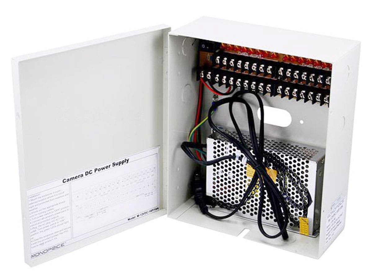
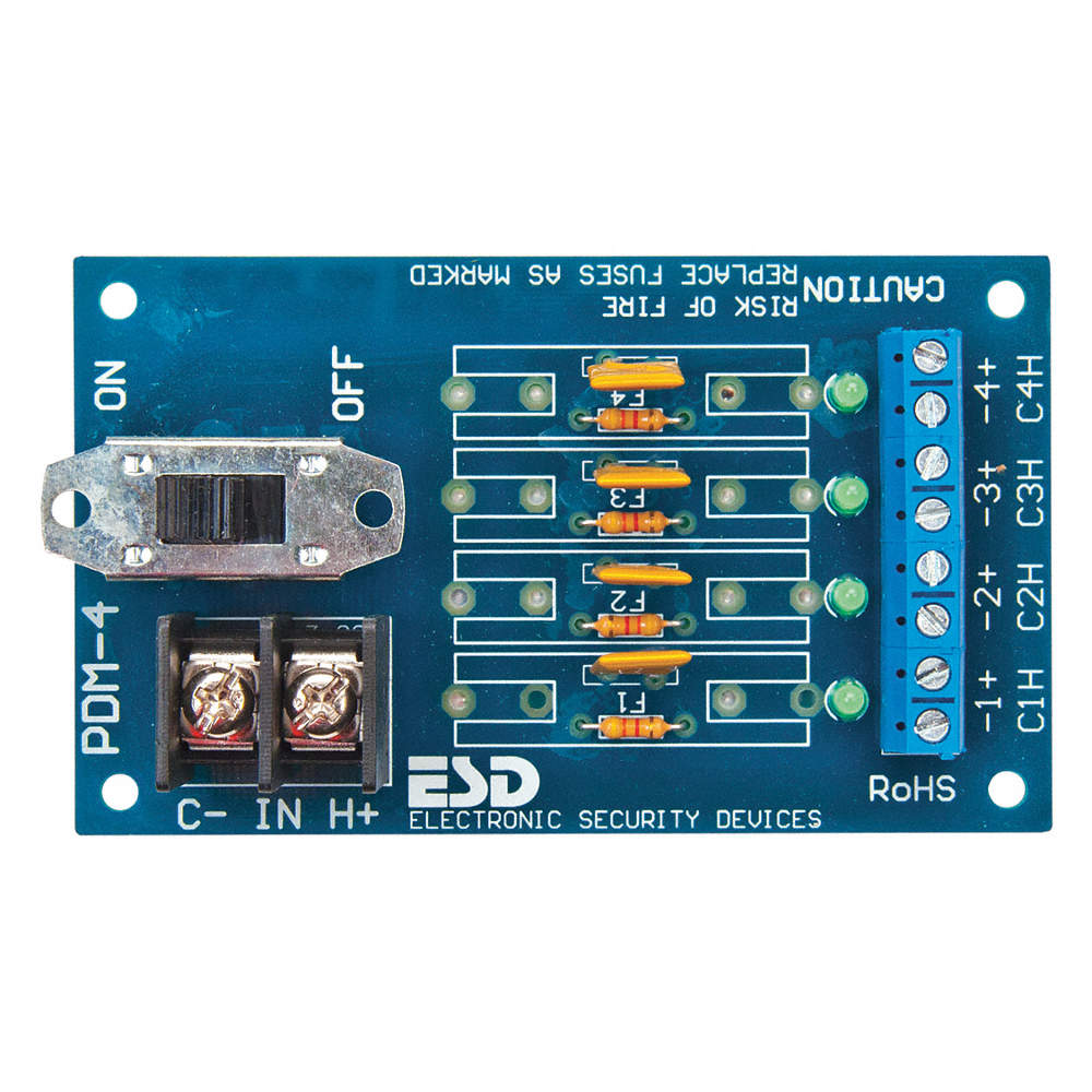
Here is a handy box for DIY escape room builders. https://www.monoprice.com/product?p_id=6875. There are better options for sure like DIN circuit breaker blocks and more specialized PTC power distribution blocks, but this is a reasonable suggestion to reduce fire potential. An alternative: https://www.grainger.com/product/48KT20.
Complications
ESD
We’ve all walked across a rug, touched something metal and received a shock. That is ESD, electrical spark discharge. Besides being annoying to us, it’s deadly to electronics. That walk across the rug or pulling scotch tape off can generate 15,000 Volts, no problem. Most small boards from Spark Fun and Adafruit contain chips which are very sensitive to ESD. Any chip is sensitive to ESD. If you are in a dry environment, you can easily blow up your Arduino boards during development. Worse, if any of the signals are accessible to your customers, they will likely zap your electronics as well.
Two things. One, keep board signals away from your customers so they can’t zap your electronics. Two, protect your circuits with a TVS.
As covered above, using the correct wire gauge for your circuits, especially your long runs on high current parts, can be detrimental. The classic example is something like a large 12V maglock that draws 1A. You want to have an emergency release for this maglock in the control room by using a disconnect switch. The control room is 50 feet away. If you run 24 AWG, only 9.4V will get to the maglock. It will probably work, but it won’t be as strong. Spend the extra few dollars on the 16 AWG and get 11.6V to your maglock. Also note, that if your maglock was running 24V, you could run 18 AWG.
Loss of voltage in DC electronics is a very real problem which can cause headaches and other problems later. Wires are not perfect. They have small resistances that add up significantly over distance.
Any large room or room with long runs should just run 24V to keep your life simpler.
Back EMF
EMF is short for electromotive force. Big word, but all it means is back current. When an inductor is powered, a EMF passes through it. When it turns off, a back EMF passes through it. You are probably thinking you don’t care about inductors, but all of the maglocks and relays used in escape rooms are inductors. Common problems people describe are erratic behavior, system resets when I turn on or turn off something, or a lockup. If you experience these issues, you likely have a Back EMF problem.
What is happening here is that current is flowing through an inductor, which could be a relay, motor, transformer, or maglock; anything with coils of wires (which form inductors). When these devices are switched, they cause a current spike, which causes a voltage spike, and the combination cause energy to jump out of the wire and into other wires. Or the spike overloads something directly connected. Either way, it’s bad. So, what you have to do is squash the spike.
For simple circuits, a diode or TVS (transient voltage suppression) can be inserted to prevent back EMF.
MOVs (metal oxide varistors) are also an option. You see these inside a quality maglock, but sometimes they are not sufficient especially when you have long cable runs. https://progeny.co.uk/back-emf-suppression/
There are a lot of factors that go into a reliable electronics control system. Keeping your signal clean and accurate takes a bit of work. Input signals like switches can be susceptible to interference because they are high impedance devices. Output devices like your maglocks can cause a lot of interference. So can things like motors and other high current devices. These devices are referred to as ‘inductive’ and create current spikes when they turn on and turn off. We need to take a two-path approach, protect inputs so they are less susceptible to interference and clamp outputs so that they make less interference.
Protecting Inputs
Input circuits to a microcontroller are high impedance. This means it takes very little energy to change the voltage on the wire, and therefore, change a digital input from high to low or low to high. A typical situation is running a switch to an input on an Arduino.
It seems so convenient as the Arduino has built in pull-ups and one just needs to pull the line low with a switch and you’re done! No! There are many things wrong with this. One, the internal pull-up is only 20K on a good day and can be as high as 50K. At 5V, that is 250uA to 100uA respectively. When the switch is closed, there is a solid connection to ground. When the switch is open, the input pin is very susceptible to noise (other electrical signals exerting unwanted energy onto your circuit). It is important that the input pin is driven (loaded/controlled) in both states of the switch.
Here are a few keys to keeping your system working as expected:
Add capacitance. Adding a small capacitor on your input pins can increase the loading dynamically. Capacitors are resistant to changes in voltage. Therefore, it will take more energy to change the voltage on your input pin.
Load both sides. In the case of the switch, provide a much smaller pull-up, something to draw about 5mA. For 5V, this is 1K.
Use a larger voltage swing. As explained above, 5V should only be used for short, in cabinet wiring (controller next to button). So when running control signals longer distances, use a larger voltage swing to increase noise immunity. Think of it like this, if you have a 5V signal and there is 1 volt of noise, then that’s 20% of your signal. If you have a 12V signal and get same 1 volt of noise, that is 8% of your signal. Built in immunity.
Use a proper input filter for an Arduino pin (or any 3V or 5V digital input) that uses an industrial control voltage.
Even when the electrical world is cleaned up, electronics still respond much faster than humans can. A very common practice is to write a de-bounce filter in your software. It’s nothing more than making sure an input is there repeatedly over a period of time. Reading an input as active once could be an anomaly, but reading it active 3 times over 30 milliseconds means it probably is really a person hitting that button.
Conclusion
Escape room operators tend to fall into two camps, people who want to build almost everything themselves and those who just want to write checks. Here at Escape Room Techs, we want to enable both – we love building things, and we particularly love helping people build things right. Keeping escape rooms safe is key to the growth of our industry.
Whether you’re a do-it-yourselfer or not, it’s your responsibility to keep the public, your employees and your investment safe from damage, and that requires a comprehensive understanding of the electrical safety issues that are intrinsic to building an immersive entertainment experience. We’re always available to help!
An incomplete, helpful guide to not burning down your business.
Introduction
If you are reading this, you probably own an escape room or you want to build one. This guide aims to address the most dangerous and common issues in escape room wiring. It should be understood that the National Electrical Code (NEC) and your local ordinances should always be followed, but in practice, as soon as the inspectors leave and you get your occupational license, people tend to do whatever they want.
AC Wiring
AC is a name for the high voltage, high power electricity we commonly use in our houses and business. AC technically only describes one aspect of the electricity. Alternating Current. This electricity flows in waves, 60 Hz (Hertz or times a second) and is great for lights and transformers, but not great for electronics.
To be specific, the electricity in America is 110 Volts, AC. I’ll use ‘AC’ in a very general sense to represent this. It is usually limited to 15A (amps) or 20A based on the breaker limit (look at your breaker). 15A circuits use 14 AWG (American Wire Gauge), 20A circuits use 12 AWG. So here is why this is important. A circuit breaker is a safety device. NEC says 14 AWG wire can safely handle 15A. Safely means it won’t overheat, melt, catch fire, etc.
So, if let’s say you extend one of these circuits with some 20 AWG wire you have laying around (which is smaller and can’t carry as much current) to run a small prop. If that prop shorts out, the 20 AWG wire will have to carry the 15A for a period of time and it’s likely to melt, overheat, and catch file. LESSON: Always use the same wire gauge through the entire branch of the circuit.
Standard single phase AC power, 110V in the USA, has 3 wires. Hot (carries the current), Neutral (current return), and Ground (references the Earth, 0V). Neutral and Ground are connected at your panel. (Not your concern. I hope you aren’t in the panel, please get an electrician.) I bring this up so you know that only the Hot (Black wire in the US, 110V systems) is the one that kills you. The other two should not have any voltage on them if properly wired referenced to ground.
AC in Escape Rooms
Most people are familiar with AC current as it’s what we have in our homes; props and decorations are routinely pulled from the commercial environment, so it’s natural to just want to run 110V AC into a room… but the best practice is to prevent all access to these outlets inside your rooms.
Common sense may seem common, but in an environment where players believe anything may be part of the game, it’s your responsibility as an escape room owner to prevent access to anything dangerous and to assume players will interact with everything in the game space. Some irresponsible owners have even designed puzzles involving faux electrical outlets, complicating safety for everyone else.
You bear full responsibility for the safety of the public when you invite them into your business. Not putting AC fixtures, props, or appliances in your room helps keep the room safe. This doesn’t mean removing fluorescent lights in your drop ceiling, but it does mean you need to pay attention to objects you may not even have considered, like the potential that players might try to remove light bulbs from a table lamp, creating a hazardous situation.
The use of GFCI can increase the safety of an AC circuit. They are just not for wet locations. These ingenious devices look for electricity leaving the system. A person could be in the path where the electricity is leaving the system and this will cut power when it detects that fault state.
If you must…
AC Wiring Key Points
Minimize use of AC. Overhead fixtures are OK, but cover up plugs and convert everything else to low voltage DC.
Run your grounds. They are there for safety. It doesn’t matter if they aren’t needed for function.
Do not use Romex, it’s for houses. Use ENT (metal or metal wrapped pipe) or the blue ‘smurf pipe’ if allowed by code, other approved enclosure for running AC current. Or hire an electrician.
Restrict, tether, mount, strap, etc. your wiring. All of it (DC too). Keeping wiring from getting yanked out of their termination point increases safety a lot.
Use a GFCI. They are just not for wet locations. They increase the safety of the circuit.
Use proper junction boxes. Don’t leave a connection in midair with wire nuts on it.
In a box with mixed voltages (AC and DC), keep the AC as far from the DC as possible. You should be able to draw a virtual line down the path where they are kept separate. Generally, components that handle both AC and DC have an isolation rating of 1000V. If it doesn’t, don’t use it.
Use approved power supplies. UL/ETL labels on power supplies will ensure you are using a quality product.
Keep wiring gauge consistent. Basically, you should never be using anything less than 14 AWG wire in a 15A circuit. No less than 12 AWG in a 20A circuit. Don’t use larger than 20A circuits unless you REALLY know what you are doing.
Switch the hot. If you are going to switch AC, use a device designed for it. If you insist on using a relay off eBay you found for $3, make sure you are switching the leg that has power on it. A proper relay will have an isolation rating to ensure it’s safe. I would also consider switching both sides of the circuit for complete isolation.